13.Water Level Measurements, Aquifer Testing & Discharge Water Handling
Chapter Description
This chapter discusses the reasons, procedures and methods for water level measurements in the well and aquifer testing. It also summarizes what should be done with the discharge water from the testing process, keeping in mind potential contamination and other environmental concerns. The requirements for the Wells Regulation on measuring and reporting water levels in test holes and dewatering wells are also provided. The requirements listed in this chapter do not apply to shallow works, other exempted wells or the exempted activities discussed in Chapter 3: Exemptions: Wells, Activities & Experienced Professionals.
Regulatory Requirements ŌĆō Yield Test Exemptions
Relevant Sections ŌĆō The Wells Regulation
- Measuring Static Water Level ŌĆō Section 14.9
- Installation of Equipment ŌĆō Section 15.3
The Requirements - Plainly Stated
The Wells Regulation:
Exemption - Yield Test
The person constructing a test hole or dewatering well is exempt from performing a yield test if the static water level is measured as described below.
Measuring Static Water Level
Before the structural stage of a test hole or dewatering well is complete, the person constructing the test hole or dewatering well must:
- measure the static water level using a tape, air line or electrical device, and
- ensure that any part of the tape, air line or electrical device that comes into contact with water in the well is clean.
Reminder: The person constructing the well must record the static water level on the well record (see Chapter 15: Well Records, Documentation, Reporting & Tagging for further information).
Exemptions - Static Water Level Measuring
Measuring the static water level or testing the well yield, in a test hole or dewatering well, is not required in any of the following situations:
- the well or activity is exempt from the Wells Regulation,
- minor alteration,
- installation of a pump, or
-
an alteration that only involves:
- the removal of the casing above the ground surface so that the casing is flush with the ground surface,
- the addition of casing above the ground surface, or
- the addition or removal of a well pit.
Equipment
A person who installs equipment in a well must ensure that the equipment is clean.
Reminder: For further information on the term ŌĆ£cleanŌĆØ and ŌĆ£minor operationŌĆØ see Chapter 2: Definitions & Clarifications, Tables 2-1 and 2-3. For further information as to who is required to perform the testing on a well or, if exempt, best management practices for retaining a person to perform the testing see Chapter 3: Exemptions: Wells, Activities & Experienced Professionals and Chapter 4: Well Contractor & Well Technicians ŌĆō Licences, Responsibilities & Exemptions.
Relevant Standards
ASTM D4043-96(2004) ŌĆō ŌĆ£Standard Guide for Selection of Aquifer Test Method in Determining Hydraulic Properties by Well Techniques,ŌĆØ (DOI: 10.1520/D4043-96R04)
ASTM D5737-95(2006) ŌĆō ŌĆ£Standard Guide for Methods for Measuring Well Discharge,ŌĆØ (DOI: 10.1520/D5737-95R06)
ASTM D4044-96(2008) ŌĆō ŌĆ£Standard Test Method (Field Procedure) for Instantaneous Change in Head (Slug) Tests for Determining Hydraulic Properties of Aquifers,ŌĆØ (DOI: 10.1520/D4044-96R02)
ASTM D4630-96(2008) ŌĆō ŌĆ£Standard Test Method for Determining Transmissivity and Storage Coefficient of Low-Permeability Rocks by In Situ Measurements Using the Constant-Head Injection Test,ŌĆØ (DOI: 10.1520/D4630-96R08)
ASTM D4631-95(2008) ŌĆō ŌĆ£Standard Test Method for Determining Transmissivity and Storage Coefficient of Low-Permeability Rocks by In Situ Measurements Using the Pressure Pulse Technique,ŌĆØ (DOI: 10.1520/D4631-95R08)
ASTM D5881-95(2005) ŌĆō ŌĆ£Standard Test Method (Analytical Procedure) for Determining Transmissivity of Non-leaky Confined Aquifers by Critically Damped Well Response to Instantaneous Change in Head (Slug) Tests,ŌĆØ (DOI: 10.1520/D5881-95R05)
ASTM D5912-96(2004) ŌĆō ŌĆ£Standard Test Method (Analytical Procedure) for Determining Hydraulic Conductivity of an Unconfined Aquifer by Overdamped Well Response to Instantaneous Change in Head (Slug) Tests,ŌĆØ (DOI: 10.1520/D5912-96R04)
ASTM D5785-95(2006) ŌĆō ŌĆ£Standard Test Method (Analytical Procedure) for Determining Transmissivity of Non-leaky Confined Aquifers by Underdamped by Well Response to Instantaneous Change in Head (Slug Test),ŌĆØ (DOI: 10.1520/D5785-95R06)
Relevant Guidelines
Procedure D-5-5, Technical Guideline for Private Wells: Water Supply Assessment, by Ministry of the Environment, Last Revision, August 1996
Technical Guidance Document For Hydrogeological Studies In Support of Category 3 Applications for Permit to Take Water, Ministry of the Environment, Operations Division, April 2008
Guidance on Sampling and Analytical Methods for Use at Contaminated Sites in ░─├┼ė└└¹, ░─├┼ė└└¹ Ministry of Environment and Energy Standards Development Branch, December, 1996, ISBN-0-7778-4056-1
Relevant Sections - Additional Regulations or Legislation
- ░─├┼ė└└¹ Water Resources Act ŌĆō Subsection 30(1) Discharge of Polluting Material Prohibited (Impairment of Quality of Any Waters)
- ░─├┼ė└└¹ Water Resources Act ŌĆō Section 34 Taking of Water (Permit to Take Water)
- ░─├┼ė└└¹ Water Resources Act ŌĆō Section 53 Sewage Works (Environmental Compliance Approval)
- Environmental Protection Act ŌĆō Subsection 14(1) Prohibition, discharge of contaminant (Adverse effect)
Key Concepts
The collection of accurate water level and pumping rate data from properly constructed test holes and dewatering wells provides essential information on the aquiferŌĆÖs physical characteristics. These characteristics include the aquiferŌĆÖs hydraulic conductivity, transmissivity, specific yield, specific storage or storativity, groundwater gradients and groundwater flow velocity. The above noted characteristics help determine if an aquifer can be used for a large taking or if interference will result from a large dewatering project.
Water Level Measurements
Water levels measurements are important aspects and procedures of monitoring programs, pumping tests and hydraulic conductivity tests. The measurements are used in calculations to interpret the hydraulic characteristics of aquifers and wells. Measurements of static water levels from wells at a study site provide a current picture of groundwater flow gradients.
Pumping Tests
Pumping tests are controlled field experiments to determine the aquiferŌĆÖs hydraulic characteristics. The information obtained from the tests help provide aquifer transmissivity, hydraulic conductivity, specific storage and specific yield. The information obtained from the testing also helps assess the long term sustained yield and efficiency of a well.
There are four common types of pumping tests. They are: a step-drawdown pumping test, constant rate pumping test, pump-in test and bailer test.
Hydraulic Conductivity Tests
Field hydraulic conductivity tests are designed field experiments to determine how groundwater is flowing through a formation. This helps in the determination of groundwater flow velocity and other aquifer characteristics.
There are five common types of field hydraulic conductivity tests. They are: slug tests, packer tests, pressure tests, tracer tests and bail tests.
Handling Discharge Water
The discharged water from a test hole or dewatering well during pumping or purging must not cause an adverse effect to the natural environment or the impairment of any waters. Steps need to be taken to ensure groundwater is appropriately discharged or collected and disposed of in an approved manner.
Water Level Measurements
For groundwater and well assessments, it is important to obtain accurate water levels, including static water levels, to determine groundwater flow directions, groundwater flow velocities, seasonal variations in water levels, hydraulic conductivity, and other hydraulic characteristics of wells and aquifers.
Documenting the static water levels for all test holes and dewatering wells at a site can provide information on the changing hydraulic conditions at the site. Analysis of this information will reveal changes in flow paths over time. This information is also essential to developing an understanding of the seasonal changes in water levels and associated variability of chemical concentrations at the site.
In many cases, measurement of the water level in the well is critical to establishing the optimum flow rate for purging and sampling, and for determining the stress placed on the well by pumping
There are various types of methods and equipment to measure well water levels depending on the use of the water level data. The measurement methods are broken into the following two groups:
- manual measurements, and
- continuous (automated) measurements.
Reminder: For further information see the ŌĆ£Groundwater Level and Other Monitoring EquipmentŌĆØ section in Chapter 12: Equipment Installation.
Static Water Level Measurement
The person constructing a test hole or dewatering well is exempt from performing a yield test if the static water level is measured as described below.
The Wells Regulation - Before the structural stage of a test hole or dewatering well is complete, the person constructing the test hole or dewatering well must:
- measure the static water level using a tape, air line or electrical device, and
- ensure that any part of the tape, air line or electrical device that comes into contact with water in the well is clean.
Reminder: The person constructing the well must record the static water level on the well record (see Chapter 15: Well Records, Documentation, Reporting & Tagging for further information).
The Wells Regulation - Measuring of the static water level, or testing of the well yield, in a test hole or dewatering well is not required in any of the following situations:
- the well or activity is exempt from the Wells Regulation,
- minor alteration,
- installation of a pump, or
-
alteration that only involves:
- the removal of the casing above the ground surface so that the casing is flush with the ground surface,
- the addition of casing above the ground surface, or
- the addition or removal of a well pit
Reminder: See Chapter 12: Equipment Installation for further requirements and exemptions related to equipment installation.
Pumping Tests
While yield tests are not required for test holes or dewatering wells, there are several types of pumping tests used to determine aquifer and well hydraulic characteristics. Examples of pumping tests include constant rate and step-drawdown pumping tests.
Best Management Practice ŌĆō Selecting a Pumping Test Method
ASTM D4043-96(2005) ŌĆō ŌĆ£Standard Guide for Selection of Aquifer Test Method in Determining Hydraulic Properties by Well TechniquesŌĆØ
Best Management Practice ŌĆō Measuring Well Discharges
To obtain accurate data, the pumping rate during the test should be accurately measured and recorded. ASTM D5737-95(2006) ŌĆō ŌĆ£Standard Guide for Methods for Measuring Well DischargeŌĆØ
Reminder: A Permit to Take Water under the ░─├┼ė└└¹ Water Resources Act is required for many types of water takings (including pumping a well for a yield test or an aquifer test) that are greater than 50,000 L (11,000 Imp gal) on any one day. Therefore, the person constructing the well should estimate the taking of water during the entire test before conducting the test. If the estimate shows the test will take more than 50,000 L on any one day, then the person constructing the well needs to obtain a Permit To Take Water from the Ministry prior to construction. More information Permit to Take Water can be found on .
Best Management Practice ŌĆō Guidance on Pumping Tests for Permit to Take Water Applications
When conducting a pumping test for a hydrogeological study in support of a category 3 Permit to Take Water application, it is important to follow the information found in the Technical Guidance Document for Hydrogeological Studies in Support of Category 3 Applications for Permit to Take Water
Best Management Practice ŌĆō Guidance on Pumping Tests for Residential Subdivisions
When conducting a pumping test for a hydrogeological study in support of a proposed private services residential subdivision, it is important to follow Procedure D-5-5, Technical Guideline for Private Wells: Water Supply Assessment
Hydraulic Conductivity Tests
Hydraulic conductivity is a function of both the formation through which a fluid is moving and the fluid itself. Generally the finer the soil particle size the lower the hydraulic conductivity. Typically, both vertical and horizontal hydraulic conductivity are calculated. Hydraulic conductivity helps determine the groundwater flow velocity at a study site.
To determine field hydraulic conductivity, slug tests, bail tests, packer tests, pressure tests or tracer tests are performed on wells.
A slug test consists of removing, adding or displacing a quantity of water in a well and monitoring the change in water levels with time. A bail test is a slug test where water is removed from the well. The slug test method provides a measure of the horizontal hydraulic conductivity.
Figure 13-1: Slug Test (Falling Head Test) Using Pressure Transducer
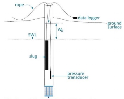
Figure 13-1 shows a cross-section of a well. A casing extends from above the ground surface into the subsurface. The bottom of the casing is attached to a well screen. A rope extends from the ground surface into the well. The bottom of the rope in the well is attached to a ŌĆ£slugŌĆØ. A datalogger is shown to the right of the well on top of the ground surface. A cable extends from the datalogger into the well. The bottom of the cable in the well is attached to a pressure transducer. A horizontal line is shown in the subsurface above the top of the slug. The horizontal line is the static water level (SWL) in the well. A horizontal line is shown above the SWL but below the ground surface. There is text on the diagram indicating this horizontal line is called the ŌĆ£WOŌĆØ (change in water level).
There is a note below the diagram that states the following:
- This shows a falling head (slug test) that consists of adding a solid slug of known volume to the well. A volume of water equal to the volume of the slug is displaced and raises the water level above the static water level (SWL). This change in water level is indicated as WO on the diagram. A pressure transducer measures the change in water level with time as it returns to the static water level (SWL).
Figure 13-2: Bail Test (Rising Head Test)
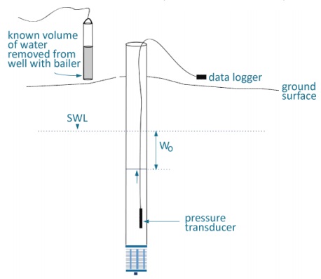
Figure 13-2 shows a cross-section of a well. A casing extends from above the ground surface into the subsurface. The bottom of the casing is attached to a well screen. A datalogger is shown to the right of the well on top of the ground surface. A cable extends from the datalogger into the well. The bottom of the cable in the well is attached to a pressure transducer. A horizontal line is shown in the subsurface above the top of the pressure transducer. The horizontal line is the static water level (SWL) in the well. A horizontal line is shown below the SWL but above the pressure transducer. There is text on the diagram indicating this horizontal line is called the ŌĆ£WOŌĆØ (change in water level). To the left of the well and above the ground surface, the diagram shows a bailer (cylinder with a volume of water) and a cable attached to the bailer. There is text beside the bailer that states ŌĆ£known volume of water removed from well with bailerŌĆØ.
There is a note below the diagram that states the following:
- This shows a rising head (bail test) that consists of removing a known volume of water from the well causing the water level to drop below the static water level (SWL). This change in water level is indicated as WO on the diagram. A pressure transducer measures the change in water level with time as it returns to the static water level (SWL).
A packer test is typically used to test hydraulic conductivity in bedrock wells. An inflatable packer or packers are used to isolate a portion of the well. Water is injected into the hole for a given length of time to test the area that has been sealed off by the packer(s). Packer tests typically involve testing multiple zones in the well. Two packer systems typically start testing at the bottom of a well and work upward. A single packer system typically tests a zone after drilling a portion of the well. Further testing occurs with the single packer as the hole is drilled deeper. An increment of pressure is applied to the zone between the packers or below a single packer. The rate of pressure decay is measured and analyzed using pressure gauges.
A tracer test involves injecting a tracer material into the well and allowing it to move away from the well into the water bearing zone. After a given period of time the well is pumped to recover the tracer. This is referred to as a single well tracer test. In other cases, nearby wells are used to detect the tracer moving through the water bearing zone. This is referred to as a multi-well tracer test. These tests are expensive and require a lot of experience in planning and interpretation.
Best Management Practice ŌĆō Guidance on Hydraulic Conductivity Tests
When using field methods to determine hydraulic conductivity, it is important to follow one or more of the following ASTM standards:
- ASTM D4044-96(2008) ŌĆō ŌĆ£Standard Test Method (Field Procedure) for Instantaneous Change in Head (Slug) Tests for Determining Hydraulic Properties of AquifersŌĆØ (DOI: 10.1520/D4044-96R02)
footnote 7 - ASTM D4630-96(2008) ŌĆō ŌĆ£Standard Test Method for Determining Transmissivity and Storage Coefficient of Low-Permeability Rocks by In Situ Measurements Using the Constant-Head Injection Test,ŌĆØ (DOI: 10.1520/D4630-96R08)
footnote 7 - ASTM D4631-95(2008) ŌĆō ŌĆ£Standard Test Method for Determining Transmissivity and Storage Coefficient of Low-Permeability Rocks by In Situ Measurements Using the Pressure Pulse Technique,ŌĆØ (DOI: 10.1520/D4631-95R08)
footnote 7 - ASTM D5881-95(2005) ŌĆō ŌĆ£Standard Test Method (Analytical Procedure) for Determining Transmissivity of Non-leaky Confined Aquifers by Critically Damped Well Response to Instantaneous Change in Head (Slug) Tests,ŌĆØ (DOI: 10.1520/D5881-95R05)
footnote 7 - ASTM D5192-96(2004) ŌĆō ŌĆ£Standard Test Method (Analytical Procedure) for Determining Hydraulic Conductivity of an Unconfined Aquifer by Overdamped Well Response to Instantaneous Change in Head (Slug) Tests,ŌĆØ (DOI: 10.1520/D5912-96R04)
footnote 7 - ASTM D5785-95(2006) ŌĆō ŌĆ£Standard Test Method (Analytical Procedure) for Determining Transmissivity of Non-leaky Confined Aquifers by Underdamped by Well Response to Instantaneous Change in Head (Slug Test),ŌĆØ (DOI: 10.1520/D5785-95R06)
footnote 7
Handling Discharge Water
Pumping Test and Purging
The discharge water from a pumping test or other aquifer test must not cause an adverse effect to the natural environment and should not interfere with the test. To reduce the risks, it is important to consider the following:
- water discharged from the well during the test should be directed a sufficient distance away from the well being pumped to minimize or eliminate recharge of this water to the aquifer during the test,
- water discharged from the well during the test should not be allowed to pond or collect near the well,
- the location of the discharge must take potential environmental impacts such as erosion into consideration, and
- potential impairment of surface water and off-site flooding should be considered (see the ŌĆ£Sewage Works ApprovalsŌĆØ section below).
Dewatering Well Discharge
Discharge water from dewatering wells must not cause an adverse effect to the natural environment. To reduce the risks, it is important to consider the following:
- water discharged from dewatering wells should not be allowed to pond or collect near the wells
- the location of the discharge to reduce potential environmental impacts such as erosion, impairment of surface water, fish habitat and off-site flooding into consideration (see the ŌĆ£Sewage Works ApprovalsŌĆØ section in this chapter).
Water from dewatering wells on contaminated sites (e.g. pump and treat systems) may be required to be collected, stored and transported to a site approved to receive the material. In certain cases, an environmental compliance approval for a sewage works will be required for on-site treatment and discharge to the natural environment (see the ŌĆ£Sewage Works ApprovalsŌĆØ section in this chapter). In other cases, permission or approval from a municipality is required to discharge the water into an approved sewer system.
Sewage Works Approvals
A sewage works environmental compliance approval under the ░─├┼ė└└¹ Water Resources Act may be required if the person discharges water off the well ownerŌĆÖs property and directly or indirectly into groundwater or surface water. It is important for the person to determine if an environmental compliance approval is required before discharging any water during a pumping or other aquifer test or as part of a dewatering project. A guide to explain the sewage works process can be found on .
Footnotes
- footnote[1] Back to paragraph ASTM International, West Conshohocken, PA, .
- footnote[2] Back to paragraph ASTM D6771-02 ŌĆō ŌĆ£Standard Practice for Low-Flow Purging and Sampling for Wells and Devices Used for Groundwater Quality Investigations. Drawdown and Water-Level Measurement,ŌĆØ (DOI: 10.1520/D6771-02). ASTM International, West Conshohocken, PA, . S.8.5, P4.
- footnote[3] Back to paragraph (DOI: 10.1520/D4043-96R04). ASTM International, West Conshohocken, PA, .
- footnote[4] Back to paragraph (DOI: 10.1520/D5737-95R06). ASTM International, West Conshohocken, PA, .
- footnote[5] Back to paragraph ░─├┼ė└└¹ Ministry of the Environment - Operations Division. April 2008. Technical Guidance Document For Hydrogeological StudiesIn Support of Category 3 Applications for Permit to Take Water. Available on .
- footnote[6] Back to paragraph ░─├┼ė└└¹ Ministry of the Environment -.August 1996. T Procedure D-5-5, Technical Guideline for Private Wells: Water Supply Assessment. Available on .
- footnote[7] Back to paragraph ASTM International, West Conshohocken, PA,